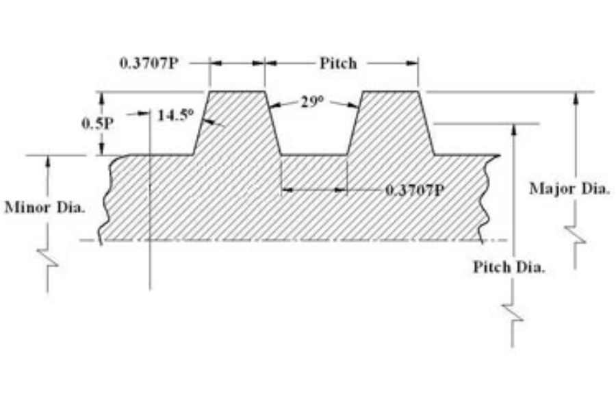
Acme threads are widely used in power transmission systems due to their efficiency, strength, and durability. They feature a trapezoidal profile that enhances their load-bearing capacity and ensures smoother movement compared to square threads. To accurately design and manufacture these threads, precise knowledge of their dimensions is essential.
Understanding the 7/8-5 Acme Thread Specifications
The designation “7/8-5” identifies an Acme thread with a nominal diameter of 7/8 inch and a pitch of 5 threads per inch. Below are the key dimensions and specifications for this thread type:
- Nominal Diameter: 7/8 inch
- Pitch: 5 threads per inch
- Thread Angle: 29 degrees
- Thread Depth: Approximately 0.125 inch (calculated based on the thread profile)
Drawing 7/8-5 Acme Threads in AutoCAD
When creating a 7/8-5 Acme thread in AutoCAD, it is crucial to accurately represent the thread profile and dimensions. Follow these steps to ensure precision:
1. Set Up Your Drawing
- Open AutoCAD and start a new drawing.
- Set the units to inches for accuracy.
2. Create the Thread Profile
- Use the LINE command to draw the trapezoidal profile of the Acme thread.
- Ensure the thread profile is symmetrical with a 29-degree angle.
3. Define Thread Dimensions
- Major Diameter: Set to 7/8 inch.
- Pitch Diameter: Typically calculated based on the pitch and thread depth. For a 7/8-5 Acme thread, you may need to refer to formulas or standards to determine the exact pitch diameter.
- Minor Diameter: Calculated based on the thread depth and major diameter. For a 7/8-5 Acme thread, this is determined by subtracting the thread depth from the major diameter.
4. Draw the Thread
- Use the ARRAY or PATTERN command to replicate the thread profile along the length of the thread.
- Adjust the spacing according to the pitch (5 threads per inch).
5. Label Dimensions
- Use the DIMLINEAR command to annotate your drawing with the major diameter, pitch, and other relevant dimensions.
6. Verify and Save
- Double-check the dimensions to ensure they align with standard Acme thread specifications.
- Save your drawing in the desired format.
Conclusion
By carefully following these steps, you can accurately create a 7/8-5 Acme thread in AutoCAD. Proper dimensioning and attention to detail are critical to ensuring that the thread will perform as intended in real-world applications. For more precise calculations and standards, consult industry guidelines and engineering references.
Unveil the latest trends and insights at Buzz Discovers.


